 Antennas
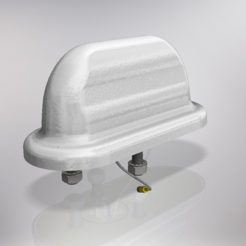
TRD4067 Train Antenna
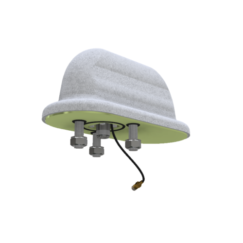
The TRD is a rugged, low profile antenna and designed for use on locomotives, buses or trucks.
This antenna has:
UHF
GSM Cellular / WiFi
GPS
with three separate connectors.
The high impact cover makes it ideal for harsh environments.
N(f), TNC(f) & SMA(f)
- Description
- Additional information
Description
The TRD4067 Train Antenna is a low-profile antenna that is robust and designed for applications on locomotives, buses, or trucks. The antenna covers the UHF, GSM cellular, and GPS bands with three separate connectors. It has a high-impact cover that makes it ideal for harsh environments. The antenna is approved for use on 50 kV railway lines.
The antenna has the following specifications: a VSWR of < 2:1 and a nominal gain of 2 dBi for the GSM cellular band, and a gain of 26 dBic (relative to an isotropic circularly polarized antenna) for the GPS band. It has a characteristic impedance of 50 Ohm. It radiates its power equally in all directions perpendicular to its axis for the UHF and GSM cellular bands. The antenna has a rated power of 8 W and 25 W in the GSM cellular and UHF bands, respectively.
The axial ratio is the ratio between the major and minor axis of the antenna. It is less than 3 dB for this specific antenna in the GPS band. It indicates how close the antenna is to a perfectly circularly polarized antenna (axial ratio of 0 dB).
The TRD4067 Train Antenna can withstand wind velocities up to 300 km/h. It weighs less than 1 kg and has a temperature range of between -30 degrees Celsius and 75 degrees Celsius.
The antenna is right-hand circularly polarized in the GPS band. This means that the electric wave rotates clockwise in a direction perpendicular to the optical axis. Both transmitting and receiving antennae must have the same polarization so that power losses in the RF system do not occur and to ensure maximum efficiency of the RF system.
The polarization of the UHF and GSM cellular bands is vertical. This means the electric field is vertical while the magnetic field is horizontal.
The antenna is mounted with 3x M10 studs. The antenna cover is made from ultraviolet-stabilized acrylonitrile butadiene styrene (ABS). The base plate is made of aluminium. The radiator is a printed circuit board (PCB). It is terminated with an N-type female connector for the UHF band and an SMA female connector for the GPS band. A TNC female connector is used for the GSM cellular band.
Additional information
| Weight | 1 kg |
|---|---|
| Dimensions | 21 × 10 × 13 cm |
| Part Number | MTTRD4067CW |
| Band Selector | |
| Additional Band Option | Cell 5G FR1, Cell GSM 1800, Cell GSM 900, Track GPS, UHF Telemetry, UHF Trunk |
| Frequency | 1575 — 1626 MHz, 1710 — 2170 MHz, 2300 — 2700 MHz, 406 — 430 MHz, 440 — 470 MHz, 698 — 960 MHz |
| Nominal Gain |